Configuring an LED display system might seem straightforward, but it involves a lot of detailed considerations. From choosing the right receiving cards and video processors to understanding how pixels are distributed across your screen, each step is important.
In this guide, we’ll walk you through the essential steps of configuring video processors and receiving cards for your LED display, offer practical examples, and highlight some common mistakes to avoid.
During the configuration process, if you have any questions, please contact LedInCloud. We are a world-leading LED Screen Cloud Platform.
Table of Contents:
1. What Are LED Video Wall Processors and LED Receiving Cards?
2. How to Configure LED Video Processors and Receiving Cards: Step-by-Step
Step 1: Understand Your LED Screen Specifications
Step 2: Determine LED Module Quantity and Layout
Step 3: Choose the Right LED Receiving Card
Step 4: Calculate Total Pixel Load for Video Processor
Step 5: Select the Right LED Video Wall Processor
3. Example Configuration Scenarios
1. What Are LED Video Wall Processors and LED Receiving Cards?
1.1 Overview of LED Display System Structure
An LED display is not a plug-and-play system. It’s a combination of several components working together: the video source (like a media player or computer), the LED video processor, the sending card, receiving cards, and finally the LED display modules. Each piece has a specific function in delivering a clean, synchronized video image across a wall of LED panels.
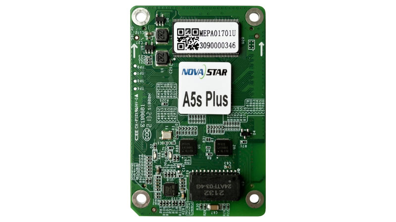
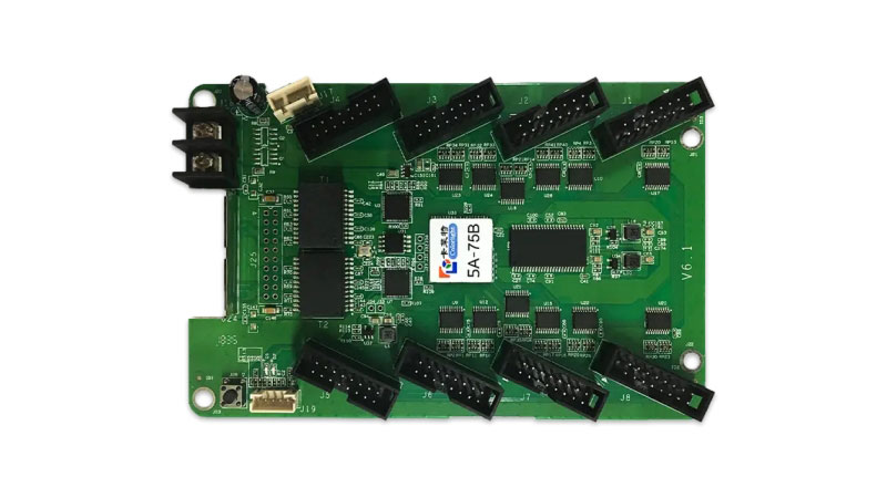
1.2 What Is a Receiving Card?
A receiving card is embedded in LED cabinets or modules. It decodes video signals from the sending card and distributes them across the LED modules. The card determines how images are mapped to each module.
(1) Interface Types:
75-pin interface: Common for standard-pitch LED modules.
320 interface: Often found in fine-pitch or small-pitch LED modules.
(2) Popular Brands:
NovaStar LED receiving card: Widely used with great software support.
Linsn receiving card: Known for reliability and performance.
Huidu receiving card: Good for budget or small projects.
Colorlight receiving card: Balanced in functionality and cost.
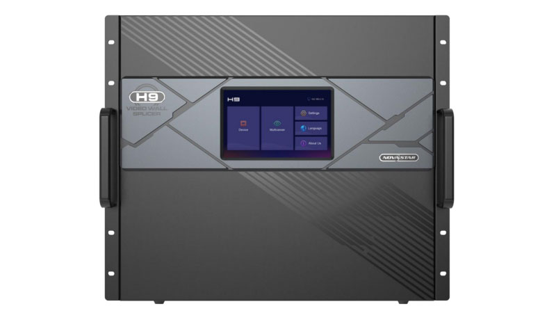
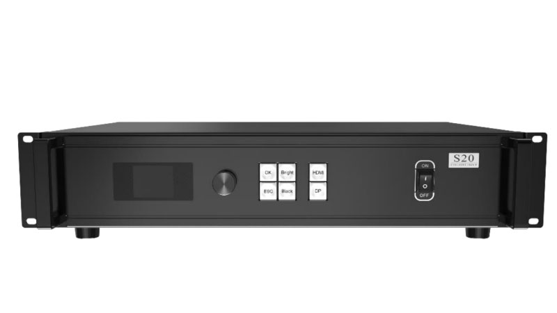
1.3 What Is an LED Video Processor?
The LED video processor is the brain of the display system. It receives and processes video signals, scaling them to match the resolution of the LED wall. It also supports input switching, multi-window displays, and format conversions.
(1) Core functions:
Scaling: Adjusts any video resolution to fit the screen layout.
Format Conversion: Handles HDMI, DVI, SDI, VGA, and other formats.
Input Switching: Seamlessly switches between multiple input sources.
Image Adjustment: Enhances brightness, contrast, and color.
(2) Popular brands:
NovaStar processor: Excellent compatibility with Novastar cards.
Linsn video processor: Stable and easy to configure.
Amoonsky LED video processor: Affordable and simple.
Brompton LED processor: High-end, used for live events and film.
More brands, such as: Colorlight led processor, Huidu video processor, RGBlink led video processor.
1.4 Why Proper Configuration Matters
If your LED display is not configured correctly:
- Images may appear distorted or scaled incorrectly.
- Sync issues may cause video lag or flicker.
- You might overload a signal path, risking failure.
Proper pairing of receiving cards and processors helps you:
- Achieve smooth, high-resolution playback.
- Avoid bandwidth overloads.
- Optimize cost and performance balance.
2. How to Configure LED Video Processors and Receiving Cards: Step-by-Step
Properly configuring your LED display requires a clear understanding of its structure, pixel load, and hardware compatibility. Follow these five essential steps to set up your screen accurately:
Step 1: Calculate the Pixel Resolution of a Single LED Module
Before you do anything else, start by understanding the pixel resolution of one LED module. This depends on two things: the physical size of the module and the pixel pitch (the distance between two LEDs).
How to calculate:
Width in pixels = Module width (mm) ÷ Pixel pitch (mm)
Height in pixels = Module height (mm) ÷ Pixel pitch (mm)
Example 1 (P2.5 module, 320×160mm):
Width: 320 ÷ 2.5 = 128 pixels
Height: 160 ÷ 2.5 = 64 pixels
Total resolution = 128 × 64 pixels
Example 2 (P1.86 module, 320×160mm):
Width: 320 ÷ 1.86 ≈ 172 pixels
Height: 160 ÷ 1.86 ≈ 86 pixels
Total resolution = 172 × 86 pixels
This pixel count will help you figure out how much image data each module handles, which affects both your receiving card choice and video processor capacity.
Step 2: Determine Total Screen Size and Module Layout
Next, decide how large you want your screen to be—and how many modules you need to build it. This step lays the foundation for hardware planning.
How to calculate:
Horizontal module count = Total screen width ÷ Module width
Vertical module count = Total screen height ÷ Module height
Example: Let’s say you want a screen that’s 3.84m wide and 2.08m tall, and your module is 320mm × 160mm.
Horizontal: 3840mm ÷ 320mm = 12 modules
Vertical: 2080mm ÷ 160mm = 13 modules
Total modules = 12 × 13 = 156 modules
This layout not only defines the screen size but also affects how many receiving cards and processor outputs you’ll need later.
Step 3: Choose the Right LED Receiving Card
Now it’s time to match your module layout with the right receiving card. Here are the main things to look for:
Interface type:
75 interface cards are common for standard modules.
320 interface cards are typically used with small-pitch or high-density LED panels.
Number of ports:
Receiving cards come with 8, 12, or 16 output ports.
If your screen is tall (more than 12 modules vertically), go with 16-port cards.
Example:
You have a screen that’s 13 modules tall and 12 modules wide:
Each vertical column requires one receiving card (since 13 < 16)
12 columns → 12 receiving cards
If a screen is taller than 16 modules (say, 22 modules), you may need two 12-port cards per column or a specially configured setup.
Step 4: Calculate the Total Pixel Load of the Whole Screen
Why is this important? Because your video processor must handle the total number of pixels on your screen. Exceeding the processor’s capacity can cause flickering, image loss, or distorted display.
How to calculate total pixels:
Total pixels = Module resolution × Horizontal module count × Vertical module count
Example with P1.86 modules (172 × 86 pixels), 12 modules wide × 13 modules high:
Total pixels = 172 × 86 × 12 × 13 = 2,307,552 pixels
Step 5: Choose the Right Video Processor
Now that you know the total pixel load, you can pick a processor that matches your screen’s needs. Most LED video wall processors (such as from Novastar, Linsn, or Colorlight) have a maximum pixel load per output port—typically around 650,000 pixels.
How to calculate:
Total ports needed = Total screen pixels ÷ 650,000
Example:
2,307,552 ÷ 650,000 ≈ 3.55
So you’ll need a 4-port processor
Also check:
Each port must handle its assigned screen section without exceeding capacity.
For 12 modules across, assign 3 columns per port:
172 × 86 × 13 × 3 = 576,888 pixels per port
This is under the 650,000 limit → good to go
If one port ends up over 650,000, you’ll need to either increase the number of ports (e.g., go for a 6-port processor) or adjust the layout split.
Professional tip:
Always leave headroom in your configuration—don’t max out your processor or receiving card. This ensures better performance, easier upgrades, and fewer issues in long-term use.
3. Example Configuration Scenarios
Understanding LED display configuration often comes down to real-world calculations. Let’s walk through a typical setup to see how small differences in wiring and component choices can affect the entire system’s performance.
Case Study: P1.86 Indoor LED Display (13 × 13 Modules)
Suppose you are installing a P1.86 indoor LED screen, laid out as 13 modules wide and 13 modules high. Each LED module is 320×160mm.
Step 1: Calculate Pixel Resolution per Module
To find the pixel resolution of each module:
Horizontal pixels: 320 ÷ 1.86 ≈ 172
Vertical pixels: 160 ÷ 1.86 ≈ 86
So, one module contains 172 × 86 = 14,792 pixels.
Step 2: Total Screen Pixel Load
With a 13×13 layout, the total number of pixels becomes:
172 × 86 × 13 × 13 = 2,499,848 pixels
This is under the maximum load of a standard 4-port LED video processor, which can typically handle around 2.6 million pixels. At first glance, this setup seems fine.
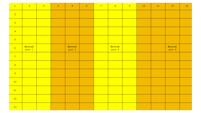
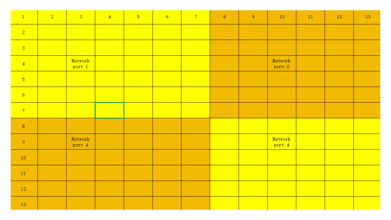
Step 3: The Real Limitation – Per-Port Load
Here’s the problem: with 13 modules horizontally, distributing them across 4 network ports is not even. One of those ports must handle data for 4 columns of modules (since 13 ÷ 4 ≈ 3.25).
Let’s calculate the load for that overloaded port:
172 × 86 × 13 (rows) × 4 (columns) = 769,184 pixels
This exceeds the per-port limit of 650,000 pixels, which is common for most processors like the Novastar VX600. Even though the total load is acceptable, this uneven distribution creates a performance risk—image instability, latency, or even failure in signal transmission.
Conclusion: Upgrade Required
In this case, the solution is to upgrade to a 6-port video processor, such as the Novastar VX1000. With more ports, the screen data can be distributed more evenly, ensuring each cable stays within safe limits.
Alternative Setup – Still Not Enough
Some users might try a more creative approach to avoid upgrading the processor. For instance:
Keep using the 4-port processor
Use two 8-port receiving cards in each column
Divide the screen into sections: one card handles 7 modules, another handles 6
Let’s check if this helps.
Recalculate the Heaviest Load Line
Say one network port is connected to 7 modules across and 7 modules high:
172 × 86 × 7 × 7 = 724,808 pixels
Again, this number is higher than the 650,000 limit.
So, even with different wiring and hardware tricks, the problem remains. The screen will still risk instability unless you switch to a processor with more output ports.
4. Common LED Configuration Mistakes
Even experienced users can run into problems when configuring LED displays, especially when managing large screens or high-resolution setups. Let’s walk through some of the most common mistakes and how to avoid them.
Mistake 1: Only Calculating Total Pixels, Ignoring Per-Port Load
One of the biggest pitfalls is assuming that as long as the total pixel count of the screen is below the maximum load of the video processor, everything will work. But in reality, each network port has its own load limit, usually around 650,000 pixels.
For example, a screen with 2.5 million pixels may seem fine for a 4-port processor that supports up to 2.6 million pixels. However, if one of the ports is carrying too much data—say over 700,000 pixels—this can lead to flickering, blackouts, or unstable playback.
How to avoid it: Always break down your layout per port. Check that no single Ethernet cable exceeds the pixel limit, even if the total is within range.
Mistake 2: Wrong Receiving Card for Your Module Interface
Not all receiving cards match all module interfaces. For example, some modules use HUB75, others use HUB320, and some may need custom adapters.
Using the wrong card can lead to:
No display output
Flickering or distorted images
Incomplete scanning or missing rows/columns
How to avoid it: Confirm your LED module’s interface type and scan mode. Then choose a receiving card that supports both. Brands like Novastar, Colorlight, and Linsn often have clear specs for this.
Mistake 3: Overloading a Single Receiving Card
Each receiving card can only handle a certain number of pixels. A common mistake is wiring too many LED modules to one card, exceeding its limit. This often happens when trying to minimize hardware costs by using fewer cards.
The result?
Laggy or delayed visuals
Overheated receiving cards
Signal loss at the edge of the screen
How to avoid it: Check the maximum pixel load per receiving card, and stick to that limit. Divide your screen logically, so no single card carries more than it should.
Mistake 4: Poor Cable Management and Long Cable Runs
In some setups, cables may stretch over long distances or twist through tight corners. This can degrade the signal—especially when using CAT5e or CAT6 Ethernet cables over 100 meters.
You might see:
Blurry image
Data loss
Random blackouts on part of the screen
How to avoid it: Keep network cables under 100 meters. Use signal extenders or fiber optic solutions for long-distance transmission. Also, label and route cables neatly for easier troubleshooting.
Mistake 5: Not Considering Redundancy
In critical applications—like live events or control rooms—no backup means high risk. If one port or card fails and there’s no redundancy setup, the whole display could go dark.
How to avoid it: Use processors and cards that support redundant signal routing. Plan for a backup port or card when designing your system.
5. Conclusion
By carefully calculating pixel resolution, choosing the right receiving card based on interface type and pixel load, and selecting a suitable video processor that matches your screen’s specifications.
Following these steps, you can smoothly set up your LED video wall system, achieving high-quality visuals, reduced maintenance costs, and an extended display lifespan.