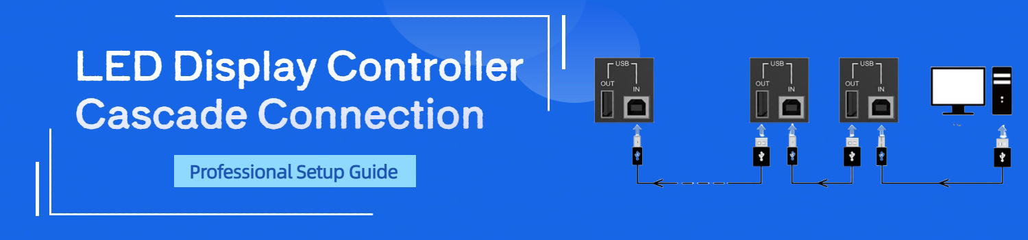
LED Display Controller Cascade Connection Professional Guide
LED display controller cascade connection is the method that links multiple controllers into one working system. Instead of controlling each unit alone, cascade makes them act as a chain, passing signals from one to the next. This approach is essential when building large video walls or high-resolution LED screens.
In this guide, we will explain what cascade connection means, how it works with popular LED screen controllers, and the key steps to verify and troubleshoot your setup.
Table of Contents
1. What is Cascade Connection in LED Display Controllers?
Cascade connection is a way to link more than one LED controller together. In a normal setup, one controller drives one screen. That works for small displays, but it has limits. When the screen is larger or the resolution is higher than one controller can handle, cascade becomes necessary.
The Principle of Cascade Connection
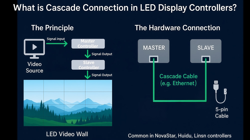
The PC or video source sends the signal to the first controller, often called the master. That master does not stop there—it passes the same signal to the next controller in the chain. Each controller then drives its own part of the LED wall. Together, they form one big picture.
Think of it like daisy-chaining. You connect the OUT port of the first controller to the IN port of the next one. The process repeats until all controllers are linked. Depending on the brand and model, this might use a 5-pin cable, an Ethernet cable, or even a USB cable.
This method is common across the industry. A NovaStar LED controller might use UART or Ethernet ports, while a Huidu LED controller or a Linsn LED controller often uses USB. The principle stays the same: master to slave, OUT to IN, one step at a time.
By using cascade, installers can build seamless LED video walls far beyond the size of a single controller. It also makes control easier. Instead of managing each box on its own, you manage the entire chain as one system.
2. Core Benefits of Cascade Connection
Cascade connection is not just a wiring trick. It brings clear benefits to anyone working with LED displays.
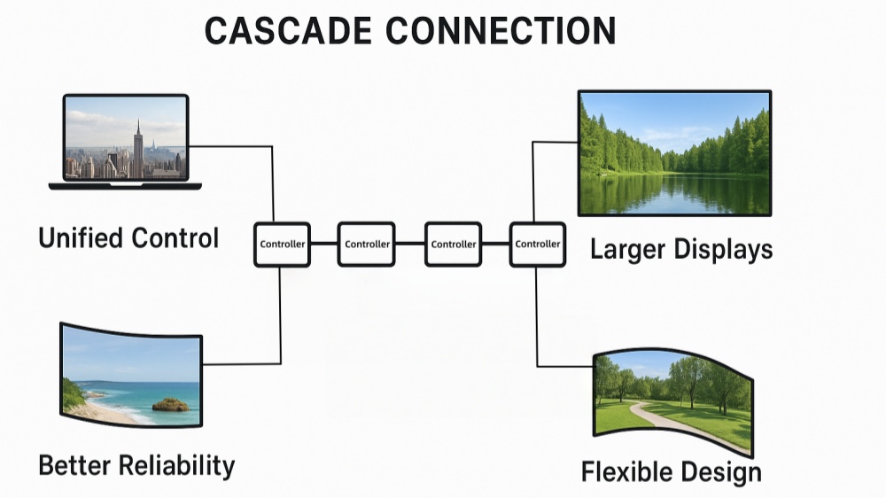
- Unified control
With cascade, you do not need to set up each controller one by one. Brightness, configuration files, or firmware updates can all be sent from the master PC to every controller in the chain. This saves time, especially when the wall has many units.
- Larger screen size
One controller has a maximum resolution. For example, a single unit might support 1920×1200 pixels. If the display is bigger, you need more controllers. Cascade removes this limit by letting multiple controllers share the same image source. It allows you to build very large LED video walls for concerts, events, or city billboards.
- Better reliability
When one controller in the chain fails, the others can still run. The screen may lose a part, but the rest keeps working. This reduces the risk of a full blackout and adds stability for important events.
- Flexible system design
Cascade makes it easier to design different shapes and sizes of screens. You can split the load between controllers based on resolution, screen layout, or installation needs.
3. Standard Setup vs. Cascade Setup
It helps to compare a normal setup with a cascade setup.
3.1 Standard setup
- One controller, one screen.
- Simple and reliable for small installations.
- Fits shop displays, small meeting rooms, or a single digital sign.
- Easy to connect and manage because there is only one box.
3.2 Cascade setup
- Multiple controllers linked in a chain.
- Needed for big video walls or screens with high pixel counts.
- Used in concerts, sports arenas, command centers, and outdoor advertising.
- Requires planning: correct order of IN and OUT ports, same firmware on each unit, and proper mapping in software.
Think of the difference like this:
A standard setup is like driving a small car—you only need one engine.
A cascade setup is like a train with several engines pulling together. Each engine handles a section, but all move as one.
By knowing the difference, you can decide when cascade is necessary. For small signs, keep it simple. For large walls, cascade is the only way to go.
4. LED Controller Cascade Connection Guide
Cascade connection is done differently by each brand. The steps depend on the model and the type of ports.
4.1 For NovaStar LED Controller
NovaStar has LED sending cards and LED controllers. Each type has its own way to cascade. Below are the most common models and how to link them.
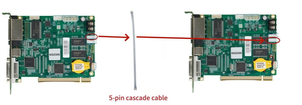
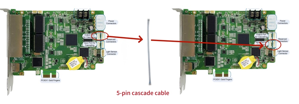
(1) Basic LED Sending Card Cascade (MSD300 / MSD600)
NovaStar MSD300 and MSD600 use a 5-pin flat cascade cable, which is usually included in the package.
Steps:
① Find the ports marked IN and OUT (for example, J6 and J18).
② Connect the OUT port of the master LED sending card to the IN port of another LED sending card using the cascade cable.
③ Repeat the process to add more LED sending cards in sequence.
④ Power on the system and check if the software detects all cards.
This method is simple and works for most small to mid-size video walls.
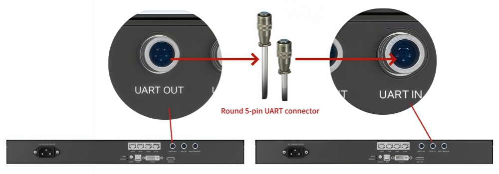
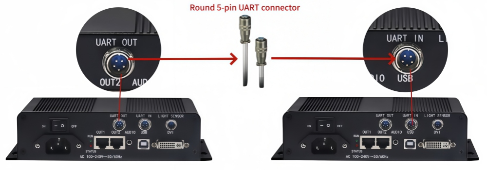
(2) LED Controller Cascade (MCTRL300 / MCTRL600)
These Controllers use a round 5-pin UART port instead of the flat connector. The principle is the same, but the cable type is different.
Steps:
① Connect UART OUT of the master controller to UART IN of the next controller using the round cable.
② Keep the chain in order.
③ Make sure connectors are locked in place, as loose cables can break the chain.
This setup is popular in rental stages because the connectors are stronger and safer for frequent handling.
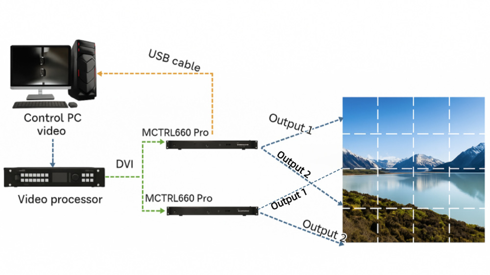
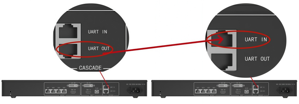
(3) Ethernet Cascade (MCTRL660)
The MCTRL660 uses standard Ethernet cables for cascade, which makes it easier to handle long distances. The ports are marked UART IN and UART OUT, even though the connectors look like LAN ports.
Steps:
① Plug an Ethernet cable from UART OUT of the master controller into UART IN of the slave controller.
② Repeat the process for more units.
③ Use high-quality CAT5e or CAT6 cables to avoid signal loss.
This design is more flexible because Ethernet cables can run longer distances without signal problems.
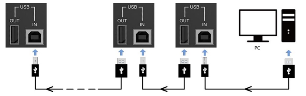
(4) USB Cascade (MCTRL R5, MCTRL 4K, NovaPro UHD, VX Series)
Many advanced NovaStar models, including MCTRL R5, MCTRL 4K, NovaPro UHD, UHD Jr, VX4s, and VX6s, use USB ports for cascade. You will find a USB OUT and a USB IN on the front or rear panel.
Steps:
① Connect USB OUT of the first controller to USB IN of the next one.
② Keep connecting controllers in the same way, OUT to IN.
③ Confirm that the control software lists all devices in order.
USB cascade is straightforward and avoids confusion, but cable length is limited. If you need longer runs, use USB extension solutions.
(5) Practical Notes for NovaStar Cascade
① Always check that all controllers run the same firmware version. If not, the wall may show tearing or sync issues.
② Match the chain order to the physical layout of the screen. For example, if the screen is built row by row, connect controllers in the same order.
③ Keep spare cascade cables in your kit. Even a single bad cable can break the whole chain.
4.2 For Colorlight, Huidu and Linsn LED Controller
Not every project uses NovaStar. Other brands such as Colorlight, Huidu, and Linsn also provide popular LED controllers. The cascade method is slightly different, but the logic is always the same: OUT goes to IN, and each device passes the signal forward.
Here is a quick overview:
| Brand | Common Models | Cascade Interface | Connection Method |
| Colorlight | S2 / S4 / S6F, X series (X4E / X6 / X8E), Z series (Z4 Pro / Z6), D series | USB ports | USB OUT → USB IN in sequence |
| Huidu | HD-T901 / HD-T902, HD-T16, HD-T08 and other huidu led controllers | USB ports | USB cable, connect IN→OUT order |
| Linsn | X104, X102, X8414, X8408, X8216, X100, X200, Y8, TS16, TS12, TS08, TS952, TS962, and many others | USB ports | USB OUT → USB IN chain |
You can explore more LED controller options and solutions on our LedInCloud – LED Screen Cloud Platform.
5. Connection Verification and Troubleshooting
After wiring the controllers in a cascade, it’s important to check if the chain is working correctly. A small mistake in cabling or software can stop the whole setup. Below are the steps to verify your connection and solve common problems.
5.1 How to Verify the Cascade Connection
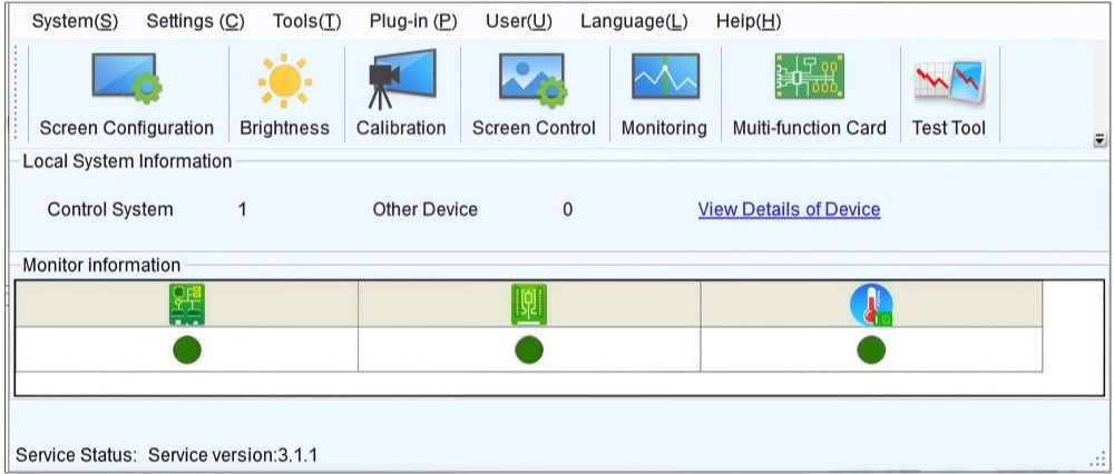
- Check software detection
- Open the LED control software on your PC.
- The software should list all controllers in the correct order.
- If you only see the master, the cascade link is not complete.
- Confirm screen response
- Load a simple test pattern (red, green, blue, or grid).
- Every section of the LED wall should light up according to its assigned controller.
- Check status indicators
- Most controllers have signal or status LEDs near the IN and OUT ports.
- A steady or blinking light usually means the signal is passing through.
- No light can mean a bad cable or port.
5.2 Common Issues and Fixes
- Problem 1: Software shows only one controller
- Make sure the cascade cable is fully inserted.
- Replace the cable to rule out damage.
- Double-check that you used OUT → IN, not IN → IN.
- Problem 2: Screen tearing or out-of-sync display
- Confirm all controllers use the same firmware version.
- Update firmware if needed so that every device runs the same build.
- Re-check the mapping in software. A wrong order can cause uneven refresh.
- Problem 3: No signal beyond a certain controller
- Test that controller by moving it to the start of the chain.
- If it works at the start but not in the middle, the OUT port may be faulty.
- If it fails completely, the unit may need repair or replacement.
- Problem 4: Flicker or unstable display
- Check the power supply. Each controller needs steady voltage.
- Make sure total power capacity covers all units.
- Keep data and power cables apart to reduce interference.
- Problem 5: USB cascade not recognized
- Remember that USB cables have length limits (usually 5 meters for passive cables).
- For longer runs, use active USB cables or extenders.
- Try a different USB port on the PC to rule out compatibility issues.
6. Design Considerations for Cascade Connection
Setting up cascade is more than just plugging cables together. For large LED walls, good planning makes the system stable and easier to maintain. Here are the main points to consider when designing a cascade setup.
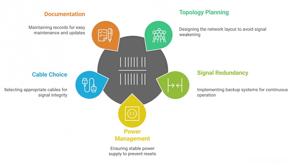
6.1 Topology Planning
Avoid long single chains: If you connect too many controllers in a row, the signal may weaken. A long chain also makes troubleshooting harder.
Use mixed structures: A practical method is to combine star and chain layouts. For example, use one main controller to start each row or column, then cascade two or three devices from it. This keeps cables shorter and the signal stronger.
Match physical layout: Arrange the cascade order to follow the actual screen layout. If the wall is built row by row, number and connect the controllers in the same sequence. This reduces confusion when mapping the screen in software.
6.2 Signal Redundancy
For important events or fixed installations, redundancy is critical.
Backup cabling: Add a second cascade line as a standby. If the main cable fails, the backup can keep the system running.
Spare controllers: In high-stakes projects, keep an extra controller in the rack. If one unit fails, it can be swapped quickly.
Dual source input: Some advanced controllers support dual input from different PCs. This allows fast switching if one source crashes.
6.3 Power and Heat Management
Calculate total load: Each controller typically consumes 5–10 watts. Add them together and check if the power supply can handle the full chain.
Stable power lines: Use dedicated power circuits for controllers instead of sharing with heavy equipment. Voltage drops can cause resets.
Cooling and airflow: Controllers generate heat, especially when stacked in racks. Provide enough airflow and consider fans for enclosed spaces.
6.4 Cable Choice and Distance
Ethernet cables: For models that use Ethernet cascade, use CAT6 or better. Shielded cables help in noisy environments like concerts or broadcast studios.
USB cables: USB cascade has a length limit (about 5 meters for passive cables). For longer distances, use active USB extension cables.
Cable labeling: Label both ends of each cable. This is a small step that saves hours during setup or troubleshooting.
6.5 Documentation and Maintenance
Keep a wiring diagram that shows every controller, port, and cable.
Record firmware versions of all controllers in use.
Update the system in stages, not all at once, to reduce risk.
7. Conclusion
LED display controller cascade connection makes it possible to build larger, more stable, and easier-to-manage LED video walls. By linking controllers in sequence, you extend screen size, keep displays in sync, and reduce setup time.
Different brands like NovaStar, Huidu, Colorlight, and Linsn use different ports, but the rule is always the same: connect OUT to IN, keep the order clear, and match the setup to your screen layout.
If you need expert support or a tailored cascade solution, contact LedInCloud can help with design and hardware advice.