
Colorlight 5A-75B vs 5A-75E Receiving Card: Specs & Comparison
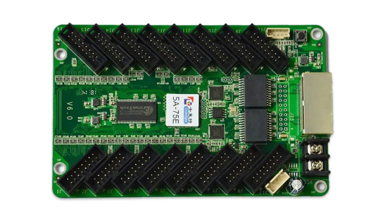
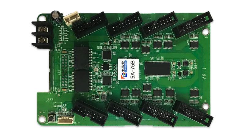
The Colorlight 5A-75B and 5A-75E are both cost-effective HUB75 receiving cards from Colorlight Cloud. They share the same basic functions, size, power consumption, and calibration features. The main difference is data capacity. The 5A-75E offers more HUB75 interfaces and a higher control area with PWM chips. If your LED display needs more data outputs or larger pixel loading under PWM chips, choose the 5A-75E. For projects with lower data requirements, the 5A-75B is the more economical option.
| Feature | Colorlight 5A-75B | Colorlight 5A-75E |
| HUB75 interfaces | 8 (J1–J8) | 16 (J1–J16) |
| Parallel data groups | Up to 16 | Up to 32 |
| Serial data groups | Up to 32 (expandable to 128) | Up to 32 (expandable to 128) |
| Control area – Normal chips | 128 × 1024 pixels | 128 × 1024 pixels |
| Control area – PWM chips | 192 × 1024 pixels | 256 × 1024 pixels |
| Control area – Shixin chips | 162 × 1024 pixels | 162 × 1024 pixels |
| Scan type | Up to 1/128 scan | Up to 1/128 scan |
| Brightness calibration | 8-bit | 8-bit |
| Chromaticity calibration | 8-bit | 8-bit |
| Loop redundancy | Supported | Supported |
| Firmware redundancy | Supported | Supported |
| Size | 145.2 × 91.7 × 18.4 mm | 145.2 × 91.7 × 18.4 mm |
| Weight | 82 g | 100 g |
| Rated power | 3.0 W | 3.0 W |
| Voltage | DC 3.8–5.5 V, 0.6 A | DC 3.8–5.5 V, 0.6 A |
The maximum control area varies with the driver chip. The exact values are covered in the specifications for each receiving card.
This table gives a quick overview of the two models. The following sections will look at the 5A-75B and 5A-75E separately, including their features, specifications, interfaces, and other details.
1. What is Colorlight 5A-75B Receiving Card?
The Colorlight 5A-75B can handle up to 192 × 1024 pixels with PWM chips and supports up to 16 groups of parallel data or 32 groups of serial data. It also provides 8 HUB75 interfaces, pixel-to-pixel calibration, and redundancy functions.

1.1 5A-75B Specifications
The control area of the 5A-75B depends on the type of LED driver chip. So, the maximum value is not the same for every LED module.
| Parameter | 5A-75B |
| Control area | 128 × 1024 pixels with normal chips |
| 192 × 1024 pixels with PWM chips | |
| 162 × 1024 pixels with Shixin chips | |
| Chip support | Normal chips, PWM chips, Shixin chips |
| Scan type | Up to 1/128 scan |
| Parallel data | Up to 16 groups |
| Serial data | Up to 32 groups |
| HUB75 interfaces | 8 |
| Module specifications | Any row and column within 13312 pixels |
| Brightness calibration | 8-bit |
| Chromaticity calibration | 8-bit |
| Cable direction | Left to right, right to left, top to bottom, bottom to top |
The 5A-75B also supports flexible data group configuration. According to the specification, the 32 groups of serial data can be expanded to 128 groups, and data groups can be exchanged freely. This gives the receiving card more flexibility when working with different LED module layouts.
1.2 5A-75B Features
The 5A-75B covers several functions that are useful during LED display setup and operation.
✔ Display performance
- 8-bit video source input and output
- Color temperature adjustment
- 240Hz frame rate
- Better grayscale performance at low brightness
- 8-bit brightness and chromaticity calibration

✔ Maintenance functions
The card includes several shortcuts that can make LED display maintenance easier:
- Cabinet highlight: Quickly identify a selected cabinet in the control software.
- Quick OSD: Display the hardware connection serial number of the receiving card.
- Image rotation: Rotate the image by 90°, 180°, or 270°.
- Data group offset: Offset the screen by data groups for simple special-shaped screens.
- Quick firmware upgrade: Update the firmware and release correction coefficients more quickly.

✔ Monitoring and redundancy
- The 5A-75B also has functions for checking communication and improving system reliability.
- Bit error monitoring: Checks the number of data packets and error packets to monitor network quality.
- Loop redundancy: Provides another communication path if one circuit fails.
- Firmware redundancy: Keeps a backup of the firmware program and supports safer firmware upgrades.
- Ethernet cable status monitoring: Helps monitor the connection status of the Ethernet cable.

1.3 5A-75B Applications
The 5A-75B is intended for LED display systems that need a receiving card with flexible data configuration and a range of display and maintenance functions. It supports different driver chips, scan types, module layouts, and cable directions, so the actual application depends on the LED module and display structure.
The specification also lists shaped screens as an optional function. The data group offset feature can be used for simple special-shaped LED screens, which adds some flexibility when the display does not follow a standard rectangular layout.
2. What is Colorlight 5A-75E Receiving Card?
The Colorlight 5A-75E is a receiving card designed for LED display systems that need a higher data capacity. It supports up to 32 groups of parallel RGB full-color data and provides 16 HUB75 interfaces. Its control area depends on the LED driver chip, with a maximum of 256 × 1024 pixels when used with PWM chips.

2.1 5A-75E Specifications
Like the 5A-75B, the 5A-75E does not have one fixed control area for every LED module. The value changes according to the driver chip used.
| Parameter | 5A-75E |
| Control area | 128 × 1024 pixels with normal chips |
| 256 × 1024 pixels with PWM chips | |
| 162 × 1024 pixels with Shixin chips | |
| Chip support | Normal chips, PWM chips, Shixin chips |
| Scan type | Up to 1/128 scan |
| Parallel data | Up to 32 groups |
| Serial data | Up to 32 groups |
| HUB75 interfaces | 16 |
| Module specifications | Any row and column within 13312 pixels |
| Brightness calibration | 8-bit |
| Chromaticity calibration | 8-bit |
| Cable direction | Left to right, right to left, top to bottom, bottom to top |
The 5A-75E supports flexible data group configuration. It can exchange data groups freely, while its serial data can be expanded to 128 groups. This is useful when the LED module layout requires a different data arrangement.
2.2 5A-75E Features
The 5A-75E includes functions for display quality, calibration, maintenance, and system monitoring.
✔ Display and calibration
- 8-bit video source input and output
- 240Hz frame rate
- Color temperature adjustment
- Low-brightness grayscale optimization
- 8-bit brightness calibration
- 8-bit chromaticity calibration
- Pixel-to-pixel calibration

✔ Maintenance functions
The 5A-75E provides several functions for LED display setup and maintenance:
- Cabinet highlighting to identify a selected cabinet in the control software
- Quick OSD to display the hardware connection serial number
- Image rotation at 90°, 180°, or 270°
- Data group offset for simple special-shaped LED screens
- Quick firmware upgrade for faster firmware updates and correction coefficient releases
These functions are particularly useful when technicians need to identify cabinets, adjust the display layout, or troubleshoot a screen during installation.
✔ Monitoring and redundancy
The 5A-75E also includes functions for monitoring data transmission and handling connection or firmware problems.
- Bit error detection monitors data packets and error packets.
- Ethernet cable status monitoring helps check the network connection.
- Loop redundancy provides an alternative communication path when one circuit fails.
- Firmware redundancy keeps a backup of the firmware program.

2.3 5A-75E Applications
The 5A-75E can be used in LED display systems where the receiving card needs more data output interfaces and a higher control capacity. Its 16 HUB75 interfaces and support for up to 32 groups of parallel data give it more output options for LED modules with higher data requirements.
It also supports different driver chips, scan types, cable directions, and module layouts. In addition, the specification lists shaped screens as an optional function, while data group offset can be used for simple special-shaped LED displays.
3. Which One Should You Choose?
The choice between the Colorlight 5A-75B and 5A-75E depends on your LED display’s actual data requirement. Both cards share the same size, power, calibration, and redundancy functions. The difference is capacity. Pick the one that matches your modules, not the one with the higher numbers on paper.
3.1 Choose the 5A-75B if:
- Your LED modules need 8 or fewer HUB75 interfaces
- The total pixel load stays within 192 × 1024 under PWM chips (or lower under normal or Shixin chips)
- 16 groups of parallel data are enough for your layout
- You want the lighter card (82 g) and a more cost-effective option
The 5A-75B is a practical choice for many standard indoor or fixed installations where data density is moderate.
3.2 Choose the 5A-75E if:
- Your LED display needs more than 8 HUB75 interfaces
- You need the higher 256 × 1024 control area with PWM chips
- You require up to 32 groups of parallel data
- The module layout is more complex or the data demand is higher
The 5A-75E gives you more headroom when the display has higher pixel density or more modules connected to one card.
Still unsure? Send us your module specification and we can help you confirm the right card.
4. How to Configure a Colorlight 5A Receiving Card?
Both the 5A-75B and 5A-75E use the same basic setup process in Colorlight’s control software (usually iSet).
Step 1: Hardware connection
Connect the receiving card to the sending card with a CAT5e cable. Power the receiving card with DC 3.8–5.5 V. Use only one of the two power connectors.
Step 2: Detect the card
Open the control software and search for the receiving card. Make sure the software shows the card as online.
Step 3: Set basic parameters
Enter the correct settings for your LED modules:
- Chip type (Normal / PWM / Shixin)
- Scan type
- Data group arrangement
- Cable direction
Step 4: Save and test
Save the configuration. Send a test pattern to check if the display works correctly.
If the image is wrong, first check the data group settings and cable direction.
Step 5: Optional functions
After the basic setup works, you can use cabinet highlight, Quick OSD, image rotation, or pixel-to-pixel calibration if needed.

5. Colorlight 5A-75B & 5A-75E Specification Download
Specification sheets contain the full technical parameters, interface definitions, and feature descriptions for each card.
You can download the latest specification files for both models here.
If you need documents or software for other Colorlight products, go to the Colorlight software download page on our site.
6. FAQs
Q1. Can I use 5A-75B and 5A-75E together in the same system?
Yes, you can mix them. Just make sure all cards run the same firmware version. Different firmware versions can cause compatibility problems.
Q2. Why does the screen flicker after I install the card?
Most of the time it comes from cable length, grounding, or incorrect data group settings. Check the CAT5e cable first (keep it ≤100 m) and confirm the data group and cable direction in the software match your modules.
Q3. What do the indicator lights mean?
• Power light (red) on = power is normal
• Signal light flashes once per second = card is working and network is normal
• Flashes 10 times per second = cabinet highlight mode
• Flashes 4 times per second = loop redundancy is active
Q4. Do I need different firmware for PWM modules?
Yes. The card needs the correct firmware that matches your driver chip (Normal, PWM, or Shixin). Using the wrong firmware is a common reason for display problems or flicker.
Q5. How do I know if the card is detected by the software?
Open the control software and click detect. If the card does not appear, first check the network cable, power supply, and whether you are using a Gigabit network connection. Poor cable quality is one of the most common causes.
7. Conclusion
The Colorlight 5A-75B and 5A-75E are both reliable HUB75 receiving cards. The 5A-75B works well for lower data requirements. The 5A-75E offers higher capacity with more interfaces and larger control area under PWM chips. Choose based on your LED module’s chip type, pixel load, and number of data outputs needed.
Need the latest specification or help selecting the right card?
Contact LedInCloud – LED Screen Cloud Platform or visit our website to get the official files.